From Idea to Market-Ready Prototype
Building a technology product is fundamentally different from building a demonstration.
A demonstration only has to prove that something can work once. A product has to work repeatedly, predictably, safely, economically, and under conditions that are not controlled by the engineer who created it.
This distinction is one of the most important lessons in physical product development.
An Arduino board connected to a sensor, a breadboard full of modules, a 3D-printed enclosure, and a laptop running a Python script may prove an idea. They do not yet constitute a product.
A real technology product is a system consisting of hardware, firmware, software, mechanics, power, interfaces, manufacturing processes, test procedures, documentation, supply-chain decisions, regulatory constraints, security decisions, and ultimately a business proposition.
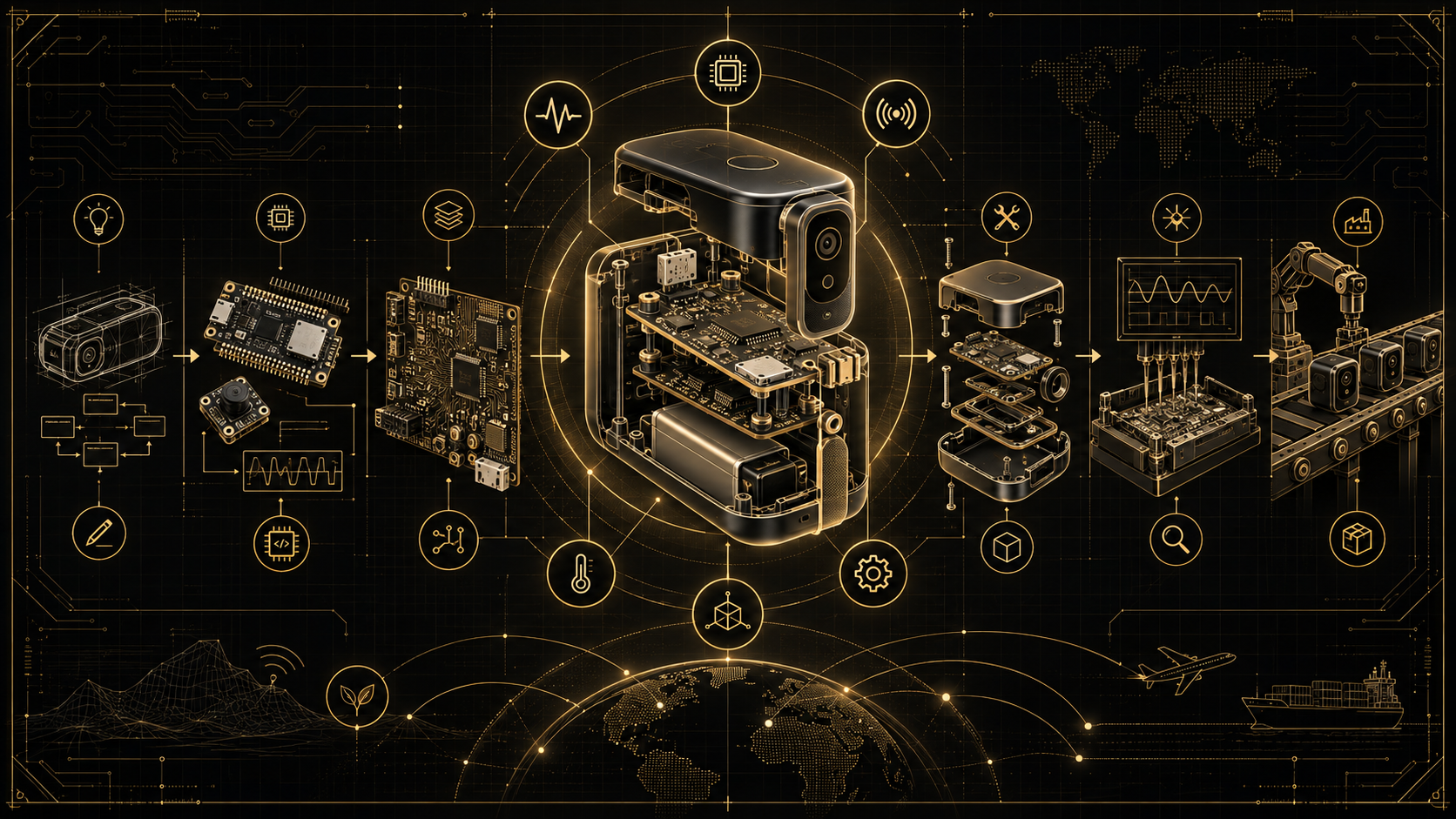
This tutorial explains the complete engineering journey from an idea to a market-ready prototype. The goal is not merely to build something that works on an engineering bench. The goal is to reach a prototype from which industrialization and commercial production can realistically begin.
1. The Real Product Development Pipeline
A useful high-level model is:
IDEA
  |
  v
PROBLEM DEFINITION
  |
  v
USER + MARKET REQUIREMENTS
  |
  v
PRODUCT REQUIREMENTS
  |
  v
TECHNICAL FEASIBILITY
  |
  v
SYSTEM ARCHITECTURE
  |
  v
PROOF OF CONCEPT
  |
  v
ENGINEERING PROTOTYPE
  |
  v
INTEGRATED PROTOTYPE
  |
  v
VERIFICATION + VALIDATION
  |
  v
DESIGN FOR MANUFACTURING
  |
  v
PRE-COMPLIANCE
  |
  v
MARKET-READY PROTOTYPE
  |
  v
EVT / DVT / PVT
  |
  v
PRODUCTION
The process is not perfectly linear. Engineering is iterative. A thermal problem may force an enclosure redesign. EMC testing may require a PCB change. A component becoming unavailable may force a firmware change. User testing may reveal that a technically elegant interface is confusing.
The purpose of a structured development process is therefore not to eliminate iteration. It is to make iteration controlled, measurable, and inexpensive.
2. Start With the Problem, Not the Technology
A common engineering mistake is beginning with a technology:
"I want to build something using AI."
"I want to use an STM32."
"I want to make a smart sports device."
None of these statements defines a product.
The first useful question is:
What problem exists, for whom, under what circumstances, and why is the existing solution insufficient?
A strong problem definition should identify:
- the target user;
- the situation in which the problem occurs;
- the current alternative;
- the weakness of that alternative;
- the measurable improvement the new product should create.
For example, instead of saying:
"Build an intelligent home training device."
define:
"Enable amateur athletes to perform measurable reaction and accuracy training at home without requiring a coach or a large dedicated training area."
Now engineering decisions can be evaluated against a real objective.
3. Separate the Product Idea From the Product Implementation
This is a subtle but extremely valuable principle.
The idea describes the value delivered to the user. The implementation describes how engineering delivers that value.
These should not be confused.
If the product requirement is:
"The user must receive immediate feedback after hitting a target."
the implementation could use:
- LEDs;
- a display;
- sound;
- a smartphone;
- haptic feedback;
- a combination of several interfaces.
If you define the implementation too early, you artificially restrict the design space.
4. Define User Needs Before Engineering Requirements
User needs describe what the user needs to accomplish.
Engineering requirements describe what the system must technically achieve.
Consider this user need:
"The device should be easy to move between rooms."
That is useful but not directly testable.
It may later become requirements such as:
- total mass shall be below 5 kg;
- one adult shall be able to carry the device without tools;
- setup time shall be below 120 seconds;
- no permanently installed infrastructure shall be required.
The transformation from vague needs into measurable requirements is one of the most important engineering activities in the entire project.
5. Build a Product Requirements Document
Before designing the PCB, create a Product Requirements Document, or PRD.
At minimum it should cover:
| Area | Typical Questions |
|---|---|
| Function | What must the product actually do? |
| Performance | How fast, accurate, powerful, or responsive? |
| Environment | Temperature, humidity, vibration, indoor/outdoor? |
| Power | Battery, USB, mains, external supply? |
| Connectivity | USB, BLE, Wi-Fi, Ethernet, CAN, RS-485? |
| Mechanical | Size, mass, mounting, impact resistance? |
| User Interface | Buttons, display, LEDs, app, sound? |
| Safety | Electrical, thermal, mechanical risks? |
| Security | Authentication, updates, credentials, data? |
| Manufacturing | Expected volume and manufacturing method? |
| Cost | Target BOM and manufacturing cost? |
| Compliance | Which markets and product categories? |
| Service | Repairable, replaceable, disposable? |
| Lifetime | Expected operating and storage life? |
6. Requirements Must Be Testable
A requirement such as:
"The device should respond quickly."
is poor because nobody can objectively determine whether it has been satisfied.
A better requirement is:
"The elapsed time between a valid sensor event and visible feedback shall not exceed 50 ms under normal operating conditions."
Every important requirement should eventually have a corresponding verification method.
REQ-023
Requirement:
Sensor-to-feedback latency <= 50 ms

Verification:
Oscilloscope measurement

Acceptance criterion:
Maximum measured latency <= 50 ms
This creates traceability:
USER NEED
   |
   v
PRODUCT REQUIREMENT
   |
   v
SYSTEM REQUIREMENT
   |
   v
DESIGN
   |
   v
TEST
   |
   v
EVIDENCE
7. Define the Minimum Viable Product Correctly
MVP is often misunderstood as "the cheapest prototype."
That is not the useful definition for hardware.
An MVP should contain the minimum set of capabilities necessary to test the core product hypothesis with representative users.
Separate features into:
- core value features;
- supporting features;
- future features;
- marketing features;
- engineering conveniences.
If removing a feature prevents you from testing whether users actually value the product, it probably belongs in the MVP.
8. Perform Technical Feasibility Before Product Design
Before investing heavily in custom hardware, determine whether the difficult parts are technically possible.
Create a feasibility-risk table.
| Risk | Uncertainty | Experiment |
|---|---|---|
| Sensor accuracy | Can events be detected reliably? | Bench experiment |
| Wireless latency | Can timing target be achieved? | Protocol prototype |
| Battery life | Is runtime practical? | Power model + measurement |
| Mechanical impact | Can housing survive repeated impacts? | Material prototype |
| Algorithm | Can events be classified? | Recorded-data prototype |
Test the highest-risk assumption first, not the easiest feature first.
This principle can save months of development.
9. Proof of Concept Is Not a Product Prototype
A Proof of Concept answers:
Can the critical principle work?
A prototype answers a much larger question:
Can the product architecture work as an integrated system?
A PoC may legitimately use:
- development boards;
- laboratory power supplies;
- temporary scripts;
- 3D-printed fixtures;
- external sensors;
- manual calibration.
Do not spend weeks making the PoC beautiful. Its purpose is uncertainty reduction.
10. Create the System Architecture Before the Schematic
Once feasibility has been demonstrated, define the system.
For a representative smart physical product:
                   +--------------------+
                   |   Mobile / PC App  |
                   +----------+---------+
                              |
                         BLE / Wi-Fi
                              |
+---------+       +-----------+-----------+       +---------+
| Sensors |------>| MCU / Main Processor  |------>| Outputs |
+---------+       +-----------+-----------+       +---------+
                              |
              +---------------+---------------+
              |               |               |
           Storage        Security        Diagnostics
              |
        Configuration

Power Input
    |
Protection
    |
Power Conversion
    |
+---+--------+----------+-----------+
|            |          |           |
MCU       Sensors     Radio      Actuators
Architecture should define responsibilities and interfaces before implementation details become difficult to change.
11. Partition the Product Into Subsystems
A useful decomposition might be:
- power subsystem;
- processing subsystem;
- sensing subsystem;
- actuation subsystem;
- communication subsystem;
- user-interface subsystem;
- mechanical subsystem;
- firmware platform;
- application software;
- cloud/backend if required;
- production-test subsystem.
Each subsystem should have defined inputs, outputs, responsibilities, failure modes, and interfaces.
12. Interface Definition Prevents Integration Disasters
Many projects fail during integration not because individual subsystems are bad, but because the interfaces were poorly defined.
For every interface specify:
- physical connector;
- pinout;
- voltage levels;
- maximum current;
- protocol;
- baud rate or bus speed;
- message format;
- timing;
- startup state;
- error behaviour;
- ownership of the interface.
An Interface Control Document can prevent enormous amounts of debugging later.
13. Make or Buy?
Do not design every subsystem yourself.
For each function ask:
- Does this function differentiate the product?
- Does an existing certified module solve it?
- What is the volume?
- What is the engineering cost?
- What is the recurring unit cost?
- What supply-chain dependency does the module create?
Using a wireless module may increase BOM cost but dramatically reduce RF engineering risk and development time. At higher volumes, a custom RF design may become economically attractive.
Product engineering is optimization across the entire business, not optimization of component price alone.
14. Select Components for Production, Not Only Prototyping
When selecting a microcontroller, sensor, regulator, memory device, connector, or communication module, evaluate more than electrical specifications.
Also investigate:
- lifecycle status;
- availability;
- second-source possibilities;
- lead time;
- package manufacturability;
- minimum order quantities;
- toolchain maturity;
- documentation quality;
- software ecosystem;
- temperature range;
- supplier reputation;
- counterfeit risk.
A technically excellent component that cannot be purchased reliably is a poor product component.
15. Design the Power Architecture Early
Power architecture influences almost every subsystem.
Determine:
- input voltage range;
- maximum and typical power;
- peak currents;
- startup current;
- sleep current;
- conversion efficiency;
- thermal dissipation;
- reverse-polarity protection;
- overcurrent protection;
- ESD and transient protection;
- battery charging requirements if applicable.
A basic power budget can be expressed as:
P_total = P_MCU + P_sensors + P_radio + P_actuators + P_lossesFor battery products:
Runtime_hours ~= Battery_capacity_Wh / Average_power_WReal systems require derating for converter efficiency, battery characteristics, temperature, aging, and load profile.
16. Design for Worst-Case Conditions
A circuit that works at room temperature with one laboratory unit has not yet been validated.
Consider combinations of:
- minimum supply voltage;
- maximum supply voltage;
- component tolerance;
- temperature;
- startup conditions;
- maximum load;
- noise;
- aging;
- manufacturing variation.
Nominal values are where demonstrations work. Corners are where products fail.
17. PCB Design Is a System-Level Activity
PCB design is not simply connecting schematic nets.
Placement and routing affect:
- signal integrity;
- power integrity;
- EMC;
- thermal performance;
- analog accuracy;
- RF performance;
- manufacturability;
- testability;
- mechanical integration.
Critical layout decisions include grounding strategy, return-current paths, decoupling placement, switching-current loops, high-speed impedance, analog/digital separation where appropriate, connector protection, and thermal current paths.
18. Design for Debugging
One of the most overlooked characteristics of professional hardware is observability.
Provide access to important signals through:
- test points;
- debug headers;
- UART diagnostics;
- SWD/JTAG;
- current-measurement points;
- status LEDs where useful;
- production programming connectors.
If a critical signal cannot be observed, diagnosing failures becomes slower and more expensive.
19. Firmware Architecture Matters From the Beginning
A prototype firmware project often starts as one large loop. That becomes dangerous as complexity grows.
Separate responsibilities such as:
Application
    |
State Machines
    |
Services
    |
Device Drivers
    |
HAL / BSP
    |
Hardware
Typical modules include:
- power management;
- sensor acquisition;
- communication;
- configuration;
- fault management;
- logging;
- firmware update;
- diagnostics.
20. Explicit State Machines Beat Accidental Behaviour
Physical products usually have states even when developers do not formally define them.
POWER_OFF
    |
    v
BOOT
    |
    v
SELF_TEST
    |
    +----- failure -----> FAULT
    |
    v
READY
    |
    v
ACTIVE
    |
    v
READY
Explicit state machines make startup, recovery, fault handling, and testing significantly more predictable.
21. Engineer Failure Behaviour
Do not only ask what happens when everything works.
Ask:
- What happens if a sensor disconnects?
- What happens if memory becomes corrupted?
- What happens during brownout?
- What happens if communication disappears?
- What happens if an update is interrupted?
- What happens if an actuator stalls?
- What happens if the user repeatedly power-cycles the device?
A professional product should fail in a controlled manner.
22. Watchdogs Are Not a Substitute for Good Firmware
A watchdog can recover a system from some software failures, but blindly resetting the product may hide deeper problems.
A useful recovery strategy may include:
- fault detection;
- fault logging;
- safe-state transition;
- controlled restart;
- persistent reset-reason recording;
- escalation after repeated failures.
23. Configuration and Calibration Need Architecture
Do not scatter calibration constants throughout source code.
Define structured configuration data with:
- versioning;
- defaults;
- range checking;
- integrity checking;
- migration between firmware versions;
- factory parameters;
- user parameters.
Manufacturing calibration must also be designed as a repeatable process, not a manual engineering trick.
24. Mechanical Design Is Part of the Electronic Design
The enclosure determines much more than appearance.
It affects:
- PCB dimensions;
- connector locations;
- antenna performance;
- cooling;
- impact resistance;
- water/dust protection;
- assembly sequence;
- serviceability;
- EMC behaviour;
- user perception.
Mechanical and electronic development should therefore proceed together.
25. Prototype Mechanics Intelligently
Different technologies answer different questions.
| Method | Best Use |
|---|---|
| FDM printing | Fast geometry and fit tests |
| SLA/SLS printing | Higher-detail functional prototypes |
| CNC machining | Strong precision parts |
| Laser cutting | Fast planar structures |
| Soft tooling | Low-volume representative molded parts |
| Injection molding | Production volumes after design maturity |
Do not invest in expensive production tooling while the mechanical design is still changing frequently.
26. Design for Assembly
Every screw, cable, connector, orientation, adhesive operation, and manual adjustment adds assembly time and opportunity for error.
Ask:
- Can a part be installed backwards?
- Can connectors be confused?
- Are too many screw types used?
- Does assembly require unnecessary hand soldering?
- Can cables be trapped?
- Can torque be controlled?
- Can assembly be performed without special skill?
27. Design for Manufacturing
DFM means designing the product so that the intended manufacturing process can produce it reliably and economically.
Examples include:
- using PCB geometries compatible with the selected fabricator;
- selecting assembly-friendly packages;
- avoiding unnecessary tolerance requirements;
- designing molded parts with appropriate wall thickness and draft;
- reducing difficult manual operations;
- selecting components compatible with automated assembly.
28. Design for Test
A product that works but cannot be efficiently tested is not production-ready.
Production test should influence the design itself.
Possible test access includes:
- bed-of-nails test pads;
- programming pads;
- loopback paths;
- built-in self-test;
- serial-number storage;
- calibration commands;
- diagnostic firmware modes.
29. Build a Test Fixture Before You Need One
Imagine producing 1,000 units.
How will you determine in seconds or minutes whether each one is good?
A production fixture may:
Connect DUT
    |
Power DUT
    |
Measure rails
    |
Program firmware
    |
Read identity
    |
Exercise inputs
    |
Exercise outputs
    |
Test communication
    |
Run calibration
    |
Store results
    |
PASS / FAIL
Automating this process creates repeatability and traceability.
30. Prototype in Generations
Do not expect Prototype V1 to become the final product.
A healthier strategy is:
| Generation | Primary Purpose |
|---|---|
| PoC | Prove uncertain physics or technology |
| Prototype A | Validate core electronics/functions |
| Prototype B | Integrate electronics, firmware and mechanics |
| Prototype C | Representative product experience |
| Pre-production | Validate manufacturing and compliance readiness |
Each generation should answer explicitly defined questions.
31. Keep an Engineering Issue Log
During testing, do not rely on memory.
ID: HW-037
Build: PCB Rev B
Problem:
Random reset when motor starts

Reproduction:
Motor startup at 11.5 V input

Evidence:
3.3 V rail drops to 2.71 V for 1.8 ms

Root cause:
Insufficient transient power margin

Corrective action:
Power-stage redesign

Verification:
Repeat 500 startup cycles
This transforms debugging into engineering knowledge.
32. Verification and Validation Are Different
Verification asks:
Did we build the product according to the requirements?
Validation asks:
Did we build the product users actually need for its intended use?
A device can pass every engineering specification and still be a poor product.
33. Create a Verification Matrix
| Requirement | Method | Acceptance | Result |
|---|---|---|---|
| REQ-001 | Measurement | Boot < 2 s | Pass/Fail |
| REQ-002 | Environmental test | 0–45 °C operation | Pass/Fail |
| REQ-003 | Power measurement | Sleep < 1 mA | Pass/Fail |
| REQ-004 | User test | Setup < 2 min | Pass/Fail |
A requirement without a verification method is incomplete.
34. Test Beyond Normal Operation
Professional validation should include abnormal and boundary conditions.
Examples:
- rapid power cycling;
- minimum and maximum supply;
- communication interruption;
- sensor disconnection;
- full storage;
- corrupted configuration;
- maximum workload;
- long-duration operation;
- thermal extremes;
- repeated mechanical cycles.
35. Use Instrumentation, Not Guesswork
A professional development bench may require:
- oscilloscope;
- logic analyzer;
- bench power supply;
- electronic load;
- digital multimeter;
- current profiler;
- thermal camera;
- protocol analyzer;
- RF equipment where appropriate.
Measure the system before changing the system.
36. Reliability Is Statistical
One working prototype proves very little about manufacturing variation.
As development progresses, test multiple units.
Failures that appear only occasionally may indicate:
- component tolerances;
- timing races;
- marginal power design;
- connector variation;
- mechanical stack-up;
- temperature sensitivity;
- manufacturing defects.
37. Perform FMEA Before Failures Become Expensive
Failure Mode and Effects Analysis forces the team to ask how the product can fail.
| Failure Mode | Effect | Cause | Detection | Mitigation |
|---|---|---|---|---|
| Sensor disconnected | Invalid measurement | Cable failure | Range check | Fault state |
| Overtemperature | Damage | High load | Temperature sensor | Power reduction |
| Memory corruption | Bad configuration | Interrupted write | CRC | Fallback defaults |
38. Cybersecurity Is a Product Requirement
For connected products, security should be designed into the architecture rather than added immediately before release.
Consider:
- unique device identity;
- authentication;
- authorization;
- secure credential storage;
- encrypted communication where required;
- secure firmware updates;
- firmware authenticity;
- debug-port control;
- safe factory provisioning;
- vulnerability handling;
- security update strategy;
- end-of-support planning.
39. Threat Modeling
Draw the product architecture and identify:
- assets;
- trust boundaries;
- interfaces;
- attack surfaces;
- privileged components;
- external dependencies.
Then ask what an attacker could gain by manipulating each interface.
Security should be proportional to the product's actual threat model, not added as random security features.
40. Compliance Must Start Early
Do not complete the product and only then ask which regulations apply.
Target markets and product classification influence architecture.
Depending on the product, relevant topics may include electrical safety, electromagnetic compatibility, radio equipment, hazardous substances, batteries, environmental obligations, machinery, medical-device requirements, or other sector-specific rules.
The applicable requirements must be determined for the actual product and intended market. There is no universal compliance checklist that applies to every technology product.
41. Pre-Compliance Testing Saves Redesigns
Before formal laboratory testing, perform pre-compliance work where practical.
For EMC-related development this may include:
- near-field probing;
- conducted-noise investigation;
- ESD robustness experiments;
- cable-emission investigation;
- power-transient testing.
Finding a major EMC problem while PCB changes are still inexpensive is far better than discovering it after tooling and certification scheduling.
42. Cost Engineering Starts During Architecture
Product cost is not simply the BOM.
Product Cost =
    Components
  + PCB
  + Assembly
  + Mechanical Parts
  + Cables
  + Packaging
  + Programming
  + Calibration
  + Production Test
  + Scrap
  + Manufacturing Overhead
  + Logistics
Commercial calculations may additionally need to account for development amortization, warranty, returns, distribution, support, certification, taxes, retailer margins, and other business costs.
43. Target Cost Before Selecting Components
If a product must eventually sell at a particular retail price, architecture cannot be developed without cost awareness.
Set cost targets for major subsystems.
Target Manufacturing Cost
|
+-- Electronics
+-- Mechanics
+-- Battery / Power
+-- Assembly
+-- Test
+-- Packaging
This prevents discovering after two years that the product is technically excellent but economically impossible.
44. Maintain a Real BOM
A professional BOM should include more than component references.
Useful fields include:
- internal part number;
- manufacturer;
- manufacturer part number;
- description;
- quantity;
- approved alternatives;
- supplier;
- unit cost;
- lead time;
- lifecycle status;
- assembly notes.
45. Supply Chain Is an Engineering Constraint
Ask what happens if a critical component disappears for six months.
For high-risk components:
- identify alternatives;
- avoid unnecessary single-source dependency;
- monitor lifecycle status;
- understand redesign impact;
- consider strategic inventory where justified.
46. Configuration Management Prevents Chaos
A prototype should have a reproducible identity.
For example:
Product: PX-01
Hardware: Rev C
Firmware: 0.8.4
Bootloader: 1.1.0
Mechanical: Rev B
PCB Assembly BOM: 0.7
Test Procedure: TP-014 Rev 3
Without configuration management, test results become ambiguous because nobody knows exactly what was tested.
47. Version Everything Important
Version control is not only for software.
Control:
- schematics;
- PCB;
- firmware;
- mechanical CAD;
- BOM;
- requirements;
- test procedures;
- production scripts;
- documentation.
48. Use Design Reviews as Engineering Gates
A design review should answer whether the project is mature enough to spend the next level of money.
Useful gates include:
Concept Review
      |
Architecture Review
      |
Schematic Review
      |
PCB Review
      |
Prototype Review
      |
Verification Review
      |
Production Readiness Review
Reviews should examine evidence, unresolved risks, assumptions, and interfaces rather than becoming presentation ceremonies.
49. Understand EVT, DVT and PVT
Hardware organizations commonly use engineering, design, and production validation stages, although exact definitions differ between companies.
EVT — Engineering Validation Test
Focuses primarily on whether the engineering architecture and core implementation work correctly.
DVT — Design Validation Test
Uses increasingly representative hardware to demonstrate that the design satisfies product requirements across intended conditions.
PVT — Production Validation Test
Validates the manufacturing process, tooling, fixtures, assembly instructions, test process, yield, and production flow using production-intent processes.
These are not merely three batches of prototypes. They represent different questions and risk categories.
50. The Market-Ready Prototype
A market-ready prototype is not necessarily mass-production-ready, but it should be close enough to the intended product that meaningful product, user, investor, partner, and engineering decisions can be made from it.
It should normally demonstrate:
- representative core functionality;
- integrated custom electronics;
- stable firmware;
- representative mechanics;
- representative user interaction;
- credible power architecture;
- major failure handling;
- repeatable assembly;
- known BOM;
- documented technical risks;
- initial compliance strategy;
- manufacturing path;
- test strategy.
51. What Must Be Frozen and What Must Remain Flexible?
Design freeze does not mean nobody can ever change anything.
It means the configuration has reached a controlled baseline and changes now require justification, impact analysis, review, and documentation.
Late changes should be evaluated for their effects on:
- hardware;
- firmware;
- mechanics;
- tests;
- certification;
- tooling;
- inventory;
- documentation.
52. A Practical Example: Developing a Smart Training Device
To connect the concepts, consider a hypothetical smart training target.
The product detects physical impacts, measures response timing, provides immediate visual feedback, stores session statistics, and communicates with a mobile application.
Project Objective
Develop a portable training product capable of detecting target impacts, measuring timing, presenting immediate feedback, and transferring training results to a companion application.
System Architecture
                    Smartphone
                        |
                       BLE
                        |
                +-------+-------+
                | Main MCU      |
                +---+--------+--+
                    |        |
                  SPI       GPIO
                    |        |
              +-----+--+   LEDs/Buzzer
              | Storage|
              +--------+
                    |
                   ADC
                    |
             Signal Conditioning
                    |
               Impact Sensor

USB-C / Battery
       |
Protection + Charger
       |
Power Management
       |
3.3 V / Other Rails
Hardware Requirements
- microcontroller with sufficient processing resources and communication interfaces;
- impact sensor appropriate to the mechanical structure;
- analog conditioning where required;
- BLE capability;
- nonvolatile storage;
- visual and/or acoustic feedback;
- USB or battery power architecture;
- debug and production-test access.
Firmware Architecture
main()
 |
 +-- platform_init()
 +-- self_test()
 +-- load_configuration()
 |
 +-- application_loop()
       |
       +-- sensor_task()
       +-- event_processor()
       +-- feedback_task()
       +-- communication_task()
       +-- storage_task()
       +-- diagnostics_task()
Reference State Machine
typedef enum
{
    STATE_BOOT,
    STATE_SELF_TEST,
    STATE_IDLE,
    STATE_SESSION,
    STATE_FAULT
} system_state_t;

static system_state_t state = STATE_BOOT;

void app_process(void)
{
    switch (state)
    {
        case STATE_BOOT:
            hardware_init();
            state = STATE_SELF_TEST;
            break;

        case STATE_SELF_TEST:
            if (self_test_run())
            {
                state = STATE_IDLE;
            }
            else
            {
                state = STATE_FAULT;
            }
            break;

        case STATE_IDLE:
            if (session_start_requested())
            {
                session_reset();
                state = STATE_SESSION;
            }
            break;

        case STATE_SESSION:
            sensor_process();
            communication_process();

            if (session_stop_requested())
            {
                session_store();
                state = STATE_IDLE;
            }
            break;

        case STATE_FAULT:
            outputs_enter_safe_state();
            diagnostics_process();
            break;

        default:
            state = STATE_FAULT;
            break;
    }
}
This is a reference architecture rather than hardware-tested firmware because actual driver calls, interrupt architecture, timing, radio stack, and hardware interfaces depend on the selected MCU and electronics.
Impact Event Processing
The raw sensor should not necessarily be converted directly into a hit event. Real sensors contain noise, ringing, mechanical coupling, and repeated threshold crossings.
A simplified processing pipeline may be:
Raw Sensor
    |
Filtering
    |
Threshold / Feature Detection
    |
Debounce / Refractory Window
    |
Event Timestamp
    |
Classification
    |
Application Event
Testing Procedure
- Verify all power rails before installing or enabling the complete firmware.
- Verify MCU programming and debug communication.
- Measure sensor output using controlled impacts.
- Determine noise floor and signal range.
- Validate event-detection thresholds.
- Measure sensor-to-feedback latency with an oscilloscope or synchronized instrumentation.
- Repeat impacts across different locations and forces.
- Test BLE connection and disconnection behaviour.
- Test interrupted power during data storage.
- Run long-duration sessions.
- Repeat testing across multiple prototype units.
Expected Results
The prototype should detect representative impacts consistently, reject normal background disturbances, provide feedback within the defined latency requirement, recover from communication loss, preserve required data, and operate without uncontrolled resets.
Typical Failures
- false impact detection caused by mechanical resonance;
- missed events because thresholds are too high;
- multiple events generated from one impact;
- power dips when feedback hardware activates;
- radio interference from poor PCB placement;
- corrupted data after interrupted writes;
- enclosure geometry changing sensor behaviour.
Debugging Procedure
For every failure:
- reproduce it;
- record the exact hardware and firmware version;
- measure relevant electrical or logical signals;
- form a testable hypothesis;
- change one relevant variable;
- repeat the test;
- identify root cause;
- implement corrective action;
- perform regression testing.
Professional Extensions
- secure firmware updates;
- factory calibration fixture;
- automated production test;
- device identity provisioning;
- advanced sensor fusion;
- cloud synchronization;
- field diagnostics;
- fleet telemetry;
- predictive maintenance where relevant.
53. The Development Documents You Should Have
By the time the market-ready prototype is complete, a serious project should have a controlled set of engineering documents.
- product requirements;
- system requirements;
- system architecture;
- interface specifications;
- risk register;
- schematics;
- PCB files;
- BOM;
- firmware repository;
- mechanical CAD;
- assembly drawings;
- verification plan;
- verification reports;
- issue log;
- FMEA or equivalent risk analysis where appropriate;
- manufacturing instructions;
- programming procedure;
- production-test specification;
- compliance plan;
- release configuration.
54. A Practical Stage-Gate Checklist
Gate 1 — Problem Validated
- target user identified;
- problem understood;
- existing alternatives studied;
- value proposition defined.
Gate 2 — Feasibility Validated
- highest technical risks tested;
- critical technologies demonstrated;
- major unknowns documented.
Gate 3 — Architecture Ready
- requirements measurable;
- system partitioned;
- interfaces defined;
- major components selected;
- cost model credible.
Gate 4 — Integrated Prototype Ready
- custom hardware operational;
- firmware stable enough for systematic testing;
- mechanics integrated;
- core user workflow operational.
Gate 5 — Design Validated
- requirements verified;
- user needs validated;
- major reliability risks understood;
- security architecture reviewed;
- pre-compliance work performed where appropriate.
Gate 6 — Market-Ready Prototype
- representative integrated units exist;
- BOM controlled;
- manufacturing approach defined;
- production test concept exists;
- known issues documented;
- industrialization roadmap defined.
55. Common Mistakes That Destroy Hardware Projects
- designing before defining requirements;
- confusing a PoC with a product;
- adding every possible feature;
- selecting components only by unit price;
- ignoring component lifecycle;
- developing electronics and mechanics independently;
- leaving security until release;
- leaving compliance until the final prototype;
- having no production-test strategy;
- testing only one unit;
- ignoring abnormal operating conditions;
- changing several variables during debugging;
- failing to version prototypes;
- building tooling before design maturity;
- optimizing prematurely;
- ignoring manufacturing tolerances;
- having no measurable acceptance criteria.
56. A Better Mental Model: Development Is Risk Retirement
One of the most useful ways to understand product development is to think of it as systematic risk retirement.
At the beginning, almost everything is uncertain:
- Does the user want it?
- Can it technically work?
- Can it be manufactured?
- Can it meet the target cost?
- Can it pass relevant compliance requirements?
- Can it survive real use?
- Can it be supported?
Every prototype, experiment, simulation, design review, and test should eliminate or reduce one of these uncertainties.
If an activity does not reduce meaningful uncertainty or create required product evidence, ask why you are doing it.
57. What "Prototype Complete" Really Means
The final question is not:
"Does it work?"
The stronger questions are:
- Does it solve the intended problem?
- Are the requirements measurable and satisfied?
- Does it work repeatedly?
- Do multiple units behave consistently?
- Are failure modes understood?
- Can it be assembled predictably?
- Can it be tested efficiently?
- Can critical components be sourced?
- Is its cost trajectory compatible with the business?
- Is there a credible regulatory path?
- Is the architecture secure enough for its threat model?
- Is there enough documentation for another engineer or manufacturer to reproduce it?
When those questions have evidence-backed answers, the project has moved far beyond a prototype that merely looks impressive. It has become an engineered product platform from which industrialization can begin.
Conclusion
The hardest part of creating a technology product is rarely designing one PCB, writing one firmware module, building one enclosure, or making one application. The real challenge is making all of these disciplines converge into one coherent system while simultaneously controlling cost, risk, manufacturability, reliability, security, compliance, and user experience.
The professional product-development mindset is therefore evidence-driven. Define what must be true. Identify what is uncertain. Test the highest-risk assumptions. Build progressively more representative prototypes. Measure rather than guess. Record failures. Find root causes. Control configurations. Validate the product as a system.
That is the transition from an idea to engineering — and from engineering to a real product.
If you are developing an embedded, electronic, robotic, IoT, or other technology-driven physical product and would like to discuss its architecture, prototyping strategy, electronics, firmware, verification, or industrialization path, please get in touch.