Walk through any modern factory and you will find IO-Link quietly doing an enormous amount of work: reading sensors, configuring them from the control room, reporting their health, and letting a failed device be swapped in seconds without a laptop. It is one of the most important — and most misunderstood — communication technologies in industrial automation. People often assume it is a fieldbus; it is not. Understanding what it actually is unlocks the whole subject.
This is a complete, zero-to-expert guide. It assumes you know nothing about IO-Link, and it is written to take you all the way to building a real, working, bidirectional system: a sensor device that produces data on one side, and a server that receives, analyses and stores that data — and sends parameters back — on the other. By the end you will understand the protocol in depth and be able to implement a project yourself.
1. What IO-Link actually is
IO-Link is a point-to-point, serial, digital communication interface for small sensors and actuators, standardised internationally as IEC 61131-9 under the name SDCI (Single-drop Digital Communication Interface). Three ideas define it:
- It is point-to-point, not a bus. One master port connects to exactly one device. This is the single most important fact — it is why IO-Link has no addressing, no bus arbitration and no termination problems.
- It runs over the ordinary sensor cable you already use. The same unshielded 3-wire cable and M12 connector that carries a simple on/off sensor signal carries IO-Link. No special cable, no shielding.
- It is a digital replacement for the analog/binary sensor connection — turning a dumb 0/24 V wire into a two-way digital channel carrying values, parameters and diagnostics.
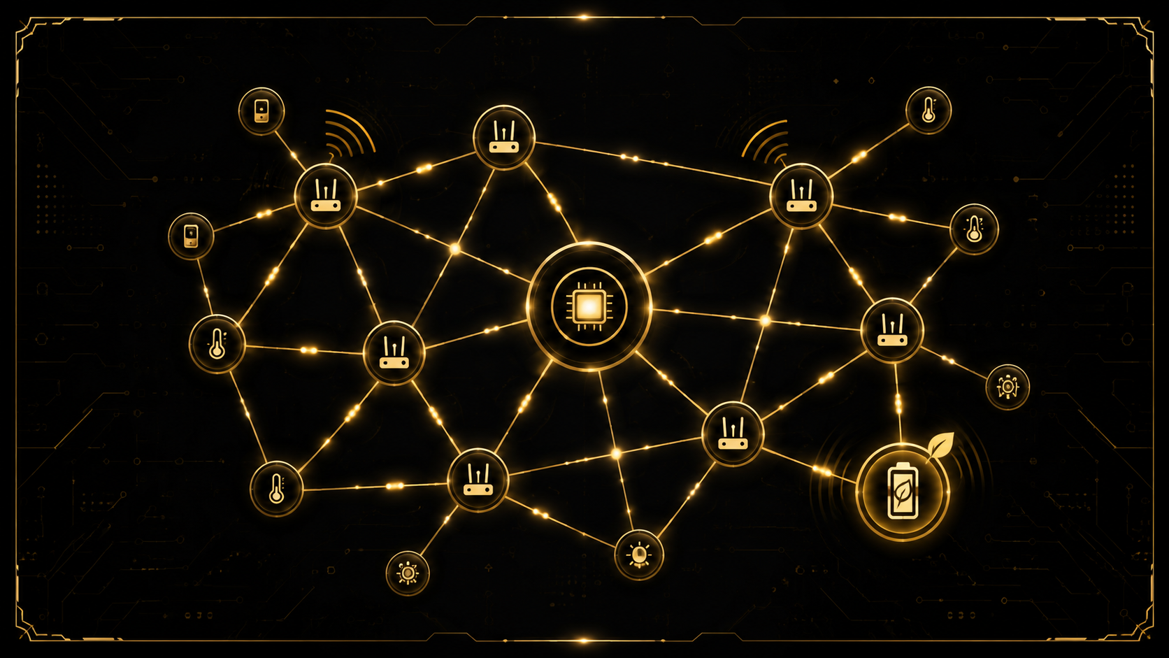
Because it is point-to-point, IO-Link is not a competitor to PROFINET, EtherCAT or EtherNet/IP. It sits below them: the sensor talks IO-Link to a master, and the master talks a fieldbus (or MQTT/OPC UA) upward to the controller. IO-Link is the 'last metre' to the sensor.
2. Why IO-Link — the value it delivers
Replacing a simple sensor wire with a digital protocol only makes sense because of what that protocol enables:
- Digital, noise-immune values. A measurement travels as digital data, so it does not degrade over the cable the way an analog 4–20 mA or 0–10 V signal can.
- Remote parameterisation. The controller can read and write a sensor's settings — thresholds, ranges, filters, teach points — over the same wire, with no one walking to the machine.
- Rich diagnostics. The device reports its identity, health, warnings and errors, enabling condition monitoring instead of silent failure.
- Automatic device replacement. With Data Storage, a replacement sensor is configured automatically from a backup the master holds — swap the part, and it just works.
- Vendor independence. IO-Link is an open standard; devices from many manufacturers work with any compliant master, described by a standard IODD file.
These benefits are why IO-Link has become a cornerstone of Industry 4.0: it is the cheapest, simplest way to get clean, self-describing, parameterisable sensor data out of the field.
3. Master and Device — and the path upward
IO-Link has exactly two roles:
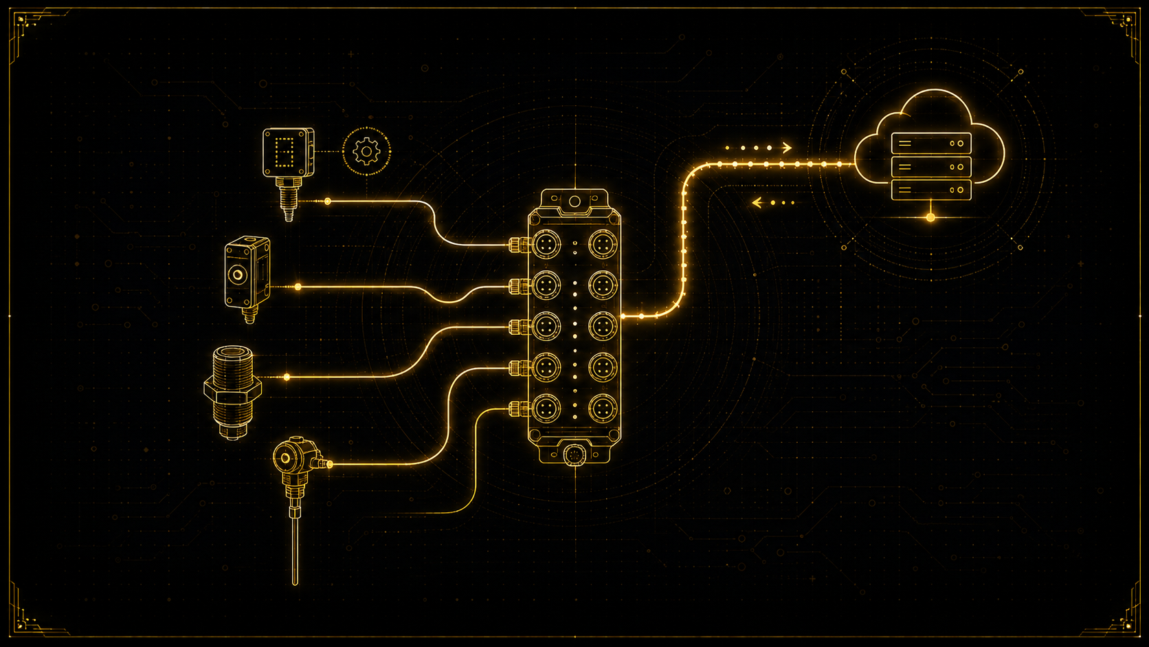
- The IO-Link Master is the active side. It has one or more ports (commonly 4 or 8), and it drives all communication — it asks, the device answers. The master also connects upward to the automation system: to a PLC over a fieldbus (PROFINET, EtherNet/IP, EtherCAT, Modbus), or to IT/cloud systems over MQTT or OPC UA through a gateway.
- The IO-Link Device is the sensor or actuator connected to one port. It is passive in the sense that it only responds to the master, but it is intelligent: it holds its own parameters, produces process data and raises events.
So a full system looks like: many devices, each on its own point-to-point link, feeding a multi-port master, which aggregates everything and presents it to the controller or the cloud. The master is the bridge between the world of individual sensors and the world of networks.
       IO-Link (point-to-point, standard 3-wire cable)
  Device 1 ───────────────┐
  Device 2 ───────────────┤
  Device 3 ───────────────┤   IO-Link      Fieldbus / MQTT / OPC UA
  Device 4 ───────────────┴──►  MASTER  ───────────────────────►  PLC / Cloud
                               (4-8 ports)
4. The physical layer: one wire does everything
IO-Link's elegance starts at the connector. A standard M12 sensor connection carries:
- L+ (pin 1): 24 V supply.
- L− (pin 3): 0 V return.
- C/Q (pin 4): the combined Communication / Switching line — the heart of IO-Link.
The C/Q line has two personalities. In SIO (Standard I/O) mode it behaves like an ordinary binary sensor output: 24 V or 0 V, a simple switching signal. In SDCI (IO-Link communication) mode the very same wire becomes a bidirectional serial line carrying framed digital messages. A single port can operate in either mode, and it starts in SIO until the master decides to 'wake up' the device into communication.
Practical limits: 24 V supply, unshielded cable up to about 20 m, and a Class A vs Class B distinction — Class A uses the standard pins, while Class B adds a separate galvanically isolated supply on pins 2 and 5 for actuators that need more power. This means IO-Link drops into existing sensor infrastructure with no rewiring — a huge reason for its adoption.
5. Communication speeds: COM1, COM2, COM3
| Mode | Baud rate | Typical use |
|---|---|---|
| COM1 | 4.8 kbit/s | Simple, slow devices |
| COM2 | 38.4 kbit/s | Common general-purpose devices |
| COM3 | 230.4 kbit/s | Fast devices, short cycle times |
A device supports exactly one of these three speeds; it is fixed by the hardware. During startup the master detects which speed the device uses, so you never configure the baud rate manually — the interface negotiates it for you.
6. Startup: wake-up, handshake, identification
When a device is plugged in, the port begins in SIO mode. To bring it online, the master runs a defined sequence:
- Wake-up. The master applies a specific pulse on the C/Q line that tells the device to switch from SIO into communication mode.
- Baud detection & handshake. The master finds the device's COM speed and the two establish a stable link.
- Identification. The master reads the device's identity — Vendor ID, Device ID, and often serial number — from fixed parameter locations.
- Verification (optional). The master can compare the connected device against the one it expects, and refuse to run if the wrong sensor is plugged in — preventing silent mis-wiring.
- Operate. The link enters cyclic operation and process data begins to flow.
All of this happens automatically in well under a second every time the device powers up or is reconnected, which is exactly what makes hot-swapping a sensor practical.
7. The three kinds of data
Everything IO-Link carries falls into three categories, and knowing the difference is the key to using it well.
Process Data (cyclic, real-time)
Process Data is the fast, cyclic payload exchanged every cycle. Process Data In flows from device to master (a sensor's measured value), and Process Data Out flows from master to device (an actuator command). Each can be up to 32 bytes, and its exact structure is defined by the device. Every cycle also carries a value-valid flag (PDValid) so the master knows the reading can be trusted.
On-request Data (acyclic, via ISDU)
On-request data is everything that does not need to be sent every cycle: parameters, identification and detailed diagnosis. It is accessed through the ISDU (Indexed Service Data Unit): the master reads or writes a value addressed by an index (and optional sub-index). This is how you configure a sensor's threshold, read its serial number, or trigger a teach-in — all without disturbing the fast process-data stream, because the master multiplexes these transfers across many cycles in the background.
Events
Events are the device's way of raising its hand: errors, warnings and notifications (for example 'short circuit', 'temperature out of range', 'maintenance required') that the device pushes to the master when something happens, rather than waiting to be asked.
8. Telegrams and frame structure
IO-Link communication is strictly master-driven: the master sends a message and the device replies. Each exchange contains a small control field that tells the device what the master wants (read or write, and which communication channel — process data, on-request data, or diagnosis), an address, the data bytes, and a checksum that protects the frame.
The amount of process data and on-request data carried per cycle is defined by the device's M-sequence type, negotiated at startup. A key consequence: a large ISDU transfer (say reading a long parameter) does not happen in one frame — the master splits it across many cycles, interleaving the acyclic bytes with the ongoing process data so the real-time stream is never interrupted. You rarely handle these frames by hand; the stack does it. But knowing that the master is continuously polling, and multiplexing acyclic data underneath the cyclic data, explains the entire timing behaviour of the protocol.
9. Minimum cycle time
Each device declares a Minimum Cycle Time — the fastest rate at which it can be polled — and the master respects it, polling no faster than the device allows. Typical values range from a few hundred microseconds for fast devices on COM3 to a few milliseconds for slower ones. The cycle time sets how fresh your process data is, and it is one of the parameters you check when a device must feed a fast control loop.
10. The IODD file — the device's machine-readable datasheet
How does a master know that byte 0–1 of a particular sensor is a temperature in 0.1 °C units, or that index 64 is its threshold? Through the IODD (IO Device Description), an XML file the device vendor provides. The IODD describes everything about the device in a standard form: its identity, the exact layout and meaning of its process data, every parameter and its ISDU index, the events it can raise, value ranges and units, and even human-readable texts and images for engineering tools.
You import a device's IODD into the master's engineering tool, and from that moment the tool knows how to display and configure the device correctly. The IODD is what makes IO-Link truly plug-and-play and vendor-neutral: any compliant tool can understand any compliant device from its description alone.
11. Data Storage — automatic device replacement
This is IO-Link's most beloved feature on the factory floor. With Data Storage, the master keeps a backup of a device's full parameter set. When a sensor fails and is replaced by an identical new one, the master automatically writes the saved parameters into the fresh device on connection — so the replacement behaves exactly like the original with no manual configuration and no laptop. A maintenance technician simply unplugs the broken sensor, plugs in a new one, and the line resumes. In a plant with thousands of sensors, this alone can justify moving to IO-Link.
12. Connecting to the world, safety and wireless
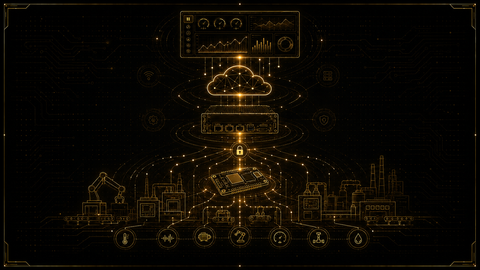
The master turns a collection of point-to-point links into something the rest of the system can use. Traditionally that means a fieldbus to a PLC — the master appears on PROFINET, EtherNet/IP, EtherCAT or Modbus and maps each port's process data into the controller. Increasingly it also means a direct path to IT and the cloud: gateways expose IO-Link data over MQTT or OPC UA, so a sensor's readings and diagnostics flow straight into dashboards, databases and analytics. This is why IO-Link is such a strong Industry 4.0 enabler — it is where clean, self-describing data begins.
Two extensions are worth knowing. IO-Link Safety adds functional-safety communication over the same interface for safety sensors and actuators. IO-Link Wireless replaces the cable with a robust radio link for moving or hard-to-wire devices while keeping the same device model. You will not need these on day one, but they show the ecosystem is complete from the simplest sensor to safety-rated and wireless applications.
13. How you actually implement IO-Link
You do not implement the raw physical signalling and M-sequences by hand — the timing is far too demanding. Real designs are built from three layers on each side.
On the device (sensor) side:
- an IO-Link device transceiver IC (for example an ADI/Maxim MAX14827/MAX14828 class part) that drives and receives the C/Q line and handles the physical layer,
- an IO-Link device stack running on a small MCU that implements the protocol (wake-up, frames, ISDU, events),
- and your application code, which simply provides process data and handles parameter reads/writes.
On the master side:
- an IO-Link master transceiver IC (for example a MAX14819 dual-port master) for the physical ports,
- a master stack that manages the ports, and
- a host (an MCU or a gateway/PC) that reads process data and issues ISDU requests, then bridges upward.
The beautiful consequence is that your job — on either side — is small and high-level: on the device you fill a buffer and answer parameter requests; on the host you read values and analyse them. The stack and transceiver hide all the hard real-time detail. That is exactly what the project below demonstrates.
14. Hands-on project: a complete bidirectional system
Now we build the real thing end to end: on one side an IO-Link device (a temperature sensor node) that sends data and accepts configuration; on the other side a server that receives, analyses and stores that data — and sends a new parameter back. In between sits an IO-Link master/gateway that bridges the point-to-point link to MQTT, so the server is a plain program that anyone can run. The full data path is:
DEVICE (sensor)            MASTER / GATEWAY               SERVER (analyzer)
 temperature  ──IO-Link──►  reads process data  ──MQTT──►  decode + analyze + store
 threshold    ◄─ISDU──────  writes parameter    ◄─MQTT──   send new threshold
     (C firmware on MCU)      (IO-Link master +          (Python program on PC / Pi)
                              MQTT bridge)
Part 1 — the device firmware (it sends data and accepts parameters)
On the sensor MCU, an IO-Link device stack does all the protocol work and calls into your application. You only implement three small callbacks: fill the process data each cycle, and answer parameter reads and writes over ISDU. Here the device reports a temperature (as a signed 16-bit value in 0.1 °C units) plus a status byte, and exposes one configurable parameter — a temperature threshold at ISDU index 64 — that the server can read and change.
/* ============ IO-Link DEVICE application (runs on the sensor MCU) ============
   The IO-Link device stack calls these functions. You only write the app logic. */

#include <stdint.h>

#define IOL_OK          0
#define IOL_ERR_INDEX  -1
#define IDX_THRESHOLD   64          /* vendor-specific parameter index */

static int16_t g_threshold_dC = 250;   /* 25.0 C default (0.1 C units) */

extern int16_t read_temperature_dC(void);        /* your sensor driver */
extern void    save_threshold(int16_t value);    /* persist to flash   */

/* (1) Fill Process Data In every cycle: 2 bytes temperature + 1 status byte */
void app_get_process_data(uint8_t *pd, uint8_t *len)
{
    int16_t t = read_temperature_dC();
    uint8_t status = 0x02;                         /* bit1 = value valid */
    if (t > g_threshold_dC) status |= 0x01;        /* bit0 = threshold exceeded */

    pd[0] = (uint8_t)(t >> 8);                     /* temperature high byte */
    pd[1] = (uint8_t)(t & 0xFF);                   /* temperature low byte  */
    pd[2] = status;
    *len  = 3;
}

/* (2) ISDU read: the master/server asks for a parameter by index */
int8_t app_isdu_read(uint16_t index, uint8_t subindex, uint8_t *buf, uint8_t *len)
{
    if (index == IDX_THRESHOLD) {
        buf[0] = (uint8_t)(g_threshold_dC >> 8);
        buf[1] = (uint8_t)(g_threshold_dC & 0xFF);
        *len   = 2;
        return IOL_OK;
    }
    return IOL_ERR_INDEX;                           /* no such parameter */
}

/* (3) ISDU write: the master/server sets a parameter */
int8_t app_isdu_write(uint16_t index, uint8_t subindex, const uint8_t *buf, uint8_t len)
{
    if (index == IDX_THRESHOLD && len == 2) {
        g_threshold_dC = (int16_t)((buf[0] << 8) | buf[1]);
        save_threshold(g_threshold_dC);            /* survives a power cycle */
        return IOL_OK;
    }
    return IOL_ERR_INDEX;
}
That is the entire device application. Notice how small it is: the stack handles wake-up, framing, checksums and timing, and calls you only to get a value or to serve a parameter. This is exactly how professional IO-Link sensors are written.
Part 2 — the master / gateway (it reads the data and bridges to MQTT)
The IO-Link master polls the device every cycle, receives those three process-data bytes, and — because we use an IIoT gateway — republishes them to MQTT. It also subscribes to a command topic so the server can push a parameter change, which the master turns into an ISDU write to the device. Many commercial IO-Link masters do exactly this out of the box; the topic scheme looks like:
MQTT topics used by the gateway
  iolink/port1/pdin      <-  raw process-data bytes as hex, e.g. "00fa02"
  iolink/gateway/command  ->  a JSON command, e.g. an ISDU write to a port
Part 3 — the server (it receives, analyses, stores and sends parameters back)
The server is a plain Python program — the same kind of MQTT subscriber used in the MQTT and Zigbee guides. It decodes the three process-data bytes into a temperature and status, logs every reading to a CSV file for analysis, prints a live view, and — closing the loop — when the sensor repeatedly exceeds its threshold, it sends a new, higher threshold back down to the device through the gateway. This is a genuinely bidirectional system: data up, parameters down.
# ============ IO-Link SERVER / analyzer (runs on a PC or Raspberry Pi) ============
# Receives process data over MQTT, analyzes and stores it, and sends parameters back.
# Install: pip install paho-mqtt

import csv, json, time
import paho.mqtt.client as mqtt

exceed_count = 0

def decode_process_data(raw: bytes) -> dict:
    """Decode the 3 process-data bytes from the device."""
    temp_dc = int.from_bytes(raw[0:2], "big", signed=True)   # 0.1 C units
    status  = raw[2]
    return {
        "temp_c":     temp_dc / 10.0,
        "exceeded":   bool(status & 0x01),   # bit0 = threshold exceeded
        "valid":      bool(status & 0x02),   # bit1 = value valid
    }

def on_connect(client, userdata, flags, reason_code, properties):
    client.subscribe("iolink/port1/pdin")
    print("Server connected, listening for process data...")

def on_message(client, userdata, msg):
    global exceed_count
    data = decode_process_data(bytes.fromhex(msg.payload.decode()))
    if not data["valid"]:
        return

    # --- store every reading for later analysis ---
    with open("iolink_log.csv", "a", newline="") as f:
        csv.writer(f).writerow([time.time(), data["temp_c"], int(data["exceeded"])])

    print(f"T = {data['temp_c']:5.1f} C   exceeded={data['exceeded']}")

    # --- analyze + act: after 5 consecutive over-threshold readings, raise the limit ---
    exceed_count = exceed_count + 1 if data["exceeded"] else 0
    if exceed_count == 5:
        new_threshold_dc = 300                      # 30.0 C
        cmd = {"port": 1,
               "isdu_write": {"index": 64,
                              "value_hex": f"{new_threshold_dc:04x}"}}
        client.publish("iolink/gateway/command", json.dumps(cmd))
        print(f"-> Sent new threshold {new_threshold_dc/10:.1f} C to the device")
        exceed_count = 0

client = mqtt.Client(mqtt.CallbackAPIVersion.VERSION2)
client.on_connect = on_connect
client.on_message = on_message
client.connect("localhost", 1883, 60)
client.loop_forever()
Part 4 — the full loop
Put together, the system runs continuously: the device measures temperature and publishes it every cycle; the master reads it and bridges it to MQTT; the server decodes, stores and analyses each reading; and when a condition is met, the server sends a parameter back down — through the gateway, as an ISDU write, into the device's app_isdu_write, where it is saved to flash and takes effect immediately. Data flows up, decisions flow down, and every layer does exactly one job. You have just built, in miniature, the architecture behind real IO-Link condition-monitoring and smart-sensor systems.
15. Best practices and common pitfalls
- Remember it is point-to-point. One device per port — there is no bus to share, so do not look for addressing.
- Always import the device's IODD into your master tool; it is the only reliable source for the process-data layout and parameter indexes.
- Keep process data small and meaningful; put configuration and rarely-changing values in parameters (ISDU), not in the cyclic stream.
- Use Data Storage so field replacement is automatic — but make sure replacement devices are truly identical (same Vendor/Device ID).
- Enable device verification where mis-wiring is a risk, so the master refuses the wrong sensor.
- Respect the minimum cycle time; do not expect data fresher than the device allows.
- Handle events, not just process data — they are how the device warns you before it fails.
- Build on a proven stack and transceiver; do not attempt the raw physical timing yourself.
16. A learning path
Take it in this order: get an IO-Link master (an evaluation kit or a small commercial 4-port master) and one IO-Link sensor; import the sensor's IODD and read its process data; use the master tool to read and write a parameter over ISDU; enable Data Storage and swap the sensor to see auto-configuration; bridge the master to MQTT or a PLC; then move to the device side — bring up a device transceiver and stack, implement the process-data and ISDU callbacks (as in the project), and finally build the full data-up / parameters-down loop. Each step is small and builds directly on the last.
Conclusion
IO-Link looks modest — a single wire to a single sensor — but it quietly transforms the field level of automation: clean digital values, remote parameterisation, real diagnostics, automatic device replacement and a direct on-ramp to the cloud, all over the cable you already have. Understand its point-to-point nature, its three kinds of data, the IODD and Data Storage, and how a master bridges upward, and the whole protocol becomes clear. And as the project showed, building with it is refreshingly high-level: the stack and transceiver do the hard real-time work, and you write the small, meaningful part.
Designing and building intelligent sensors, IO-Link devices and masters, and the firmware and gateways that turn field data into something useful, is exactly the kind of work I do. If you are developing an IO-Link product, integrating smart sensors, or building the bridge from the field to your control system or the cloud, get in touch — I would be glad to help.